A measuring wheel is a measuring device used to determine the dynamic forces and moments acting on the chassis or the vehicle in general. This can be used, for example, to determine the dimensions of the load-bearing structure or of springs and dampers.
As a development service provider, measuring wheels have been created in several projects which record the loads in the wheel and transmit them to the vehicle via a telemetry system.
Requirements
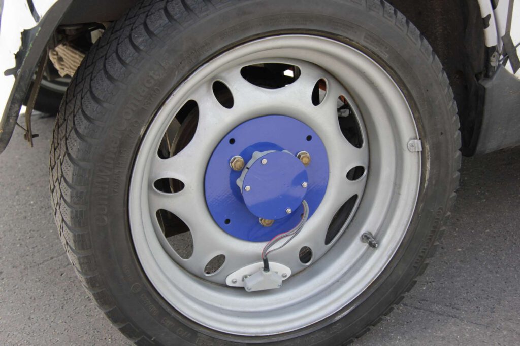
The central requirement from the specifications is an unchanged rim structure with the aim of not changing the driving dynamics by increasing the unsprung mass or reducing the stiffness of the wheel. In addition, the type approval (ABE) is retained and so test drives are legally possible in public road traffic.
Advantages over existing systems
The aim of the development was therefore not to provide the original wheel with measuring sensors, which are usually formed by deformation bodies with strain gauges or by several load cells. On the one hand, such transducers are very accurate and can measure forces in 6 axes, but on the other hand they require considerable adaptation of the rim, which leads to a significant increase of mass and a reduction of stiffness. In driving operation, this can have a negative effect on the driving dynamics and does not correspond to the original system in which the wheel forces are to be determined.
Solution
The validated solution is: indirect measurement of the strain stress in the rim of the measuring wheel and back-calculation to the external loads responsible for it.
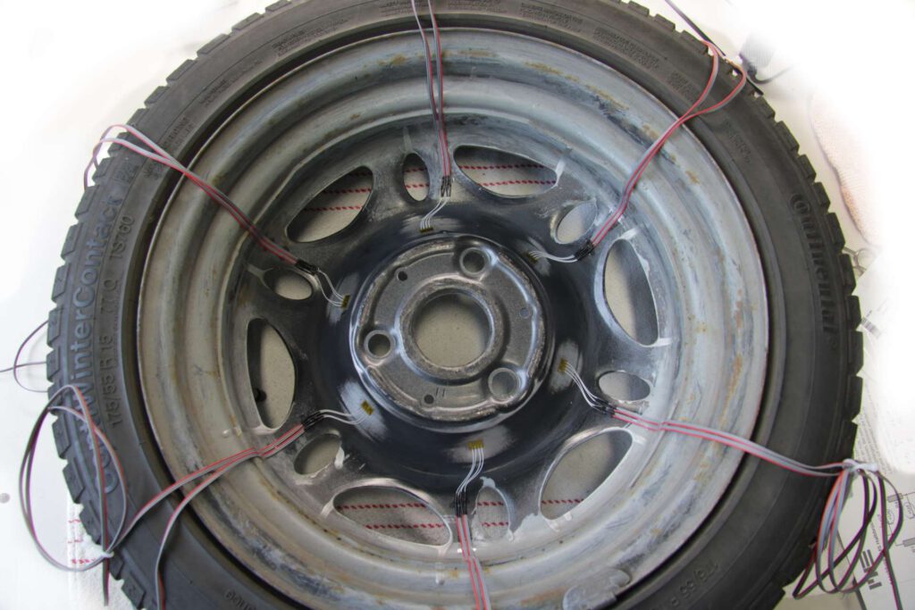
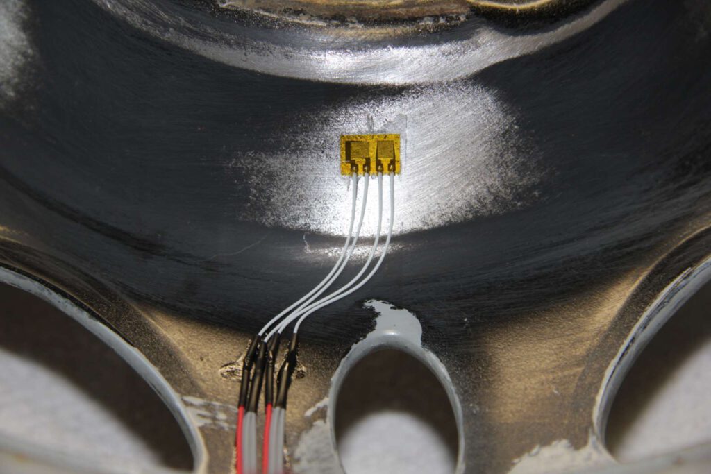
The application of the strain gages on the rim and the telemetry module must be done individually for each application, and should be done in areas of relatively large strain in order to obtain measurement signals with good signal-to-noise ratio. Of course, the measurement level is lower with a direct strain measurement on the rim than with a measuring body (measuring adapter or load cell), but with modern measuring amplifiers, high-quality measurement signals can be acquired by adjusting the measuring ranges and expertly defined filtering.
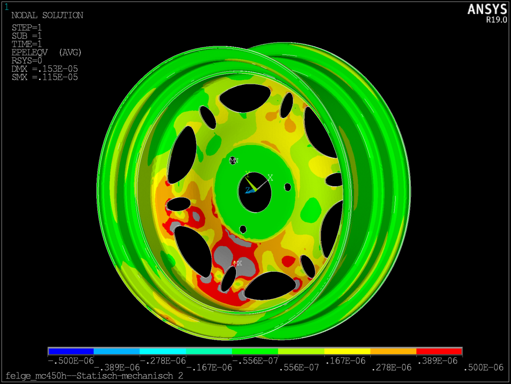
The load path from the wheel contact point via the tire and rim to the hub depends on the angular position of the wheel, which leads to alternating stresses in the rim. The relationship of the strains to the applied loads as an essential measurement result is provided by transfer matrices calculated by the finite element method (FEM). Usually, the wheel force is required in the vehicle coordinate system, which is why it has to be transformed depending on the angle.
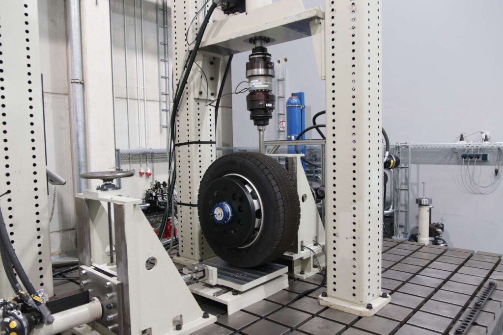
Calibration
For highest accuracies, a final calibration should be performed on the complete wheel, i.e. rim with tire. In the existing systems with measuring adapters, usually only the measuring adapter itself is calibrated in a special device, which is then also only valid for the cutting forces on the bolt surfaces. Together with IKAM GmbH and the load test rig set up there, a fully comprehensive calibration is carried out for several load directions and several wheel positions.
Conclusion
With the developed and implemented solution strategy for a measuring wheel, the following characteristics are achieved:
- + No mechanical influence on the rim: stiffness and mass remain constant
- + Rim does not have to be reworked: No need to turn out and weld in a flange for the measuring adapter
- – Comparatively lower sensitivity of the measuring system
- + No loss of type approval ABE for measurements in public road traffic
- + Low cost: telemetry and strain gauges only